CONCEPT
On complex mountainous terrain where steep slopes and irregular bumpy surfaces are prominent, the airflow near the surface is likely to become messy and non-uniform. Highly non-uniform or excessive turbulent wind flow can cause major adverse effects for turbine operation. An understanding of the turbulence risk is essential in order to achieve stable operation and high efficiency. To do that, the following four steps are recommended.
01
Determine Mast Position by LES CFD
Proper position is the first step toward success
Vector
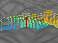
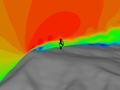
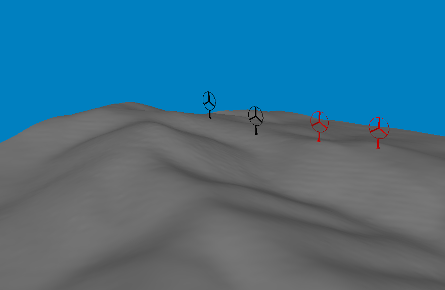
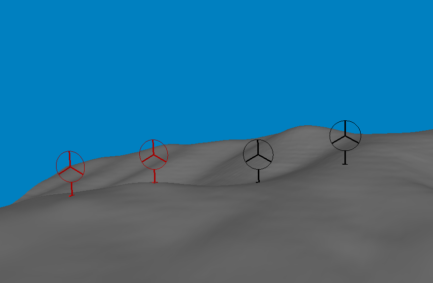
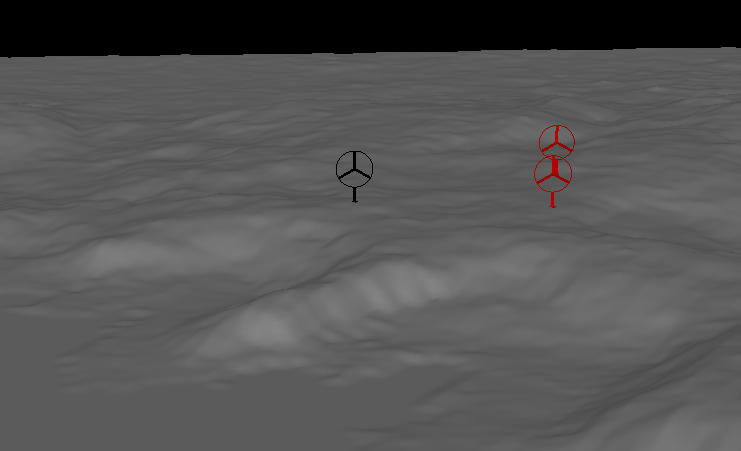
When considering mast positions for complex terrain site, it is vitally important to evaluate if the positions are under high level of turbulence or not.
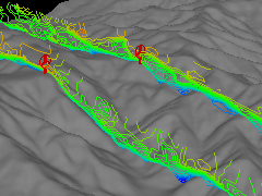
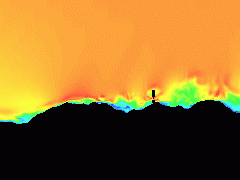
Here is a 60 meter mast installed at a location of high turbulence. Flow separation occurred in the upstream, and more than half of the mast is inside the vortex recirculation zone, resulting in extremely high wind speed fluctuations and high turbulence intensity.
Shading
Topography
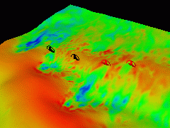
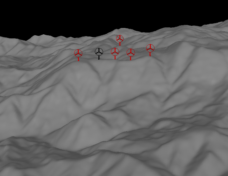
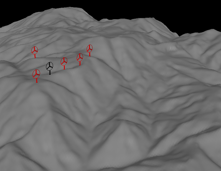
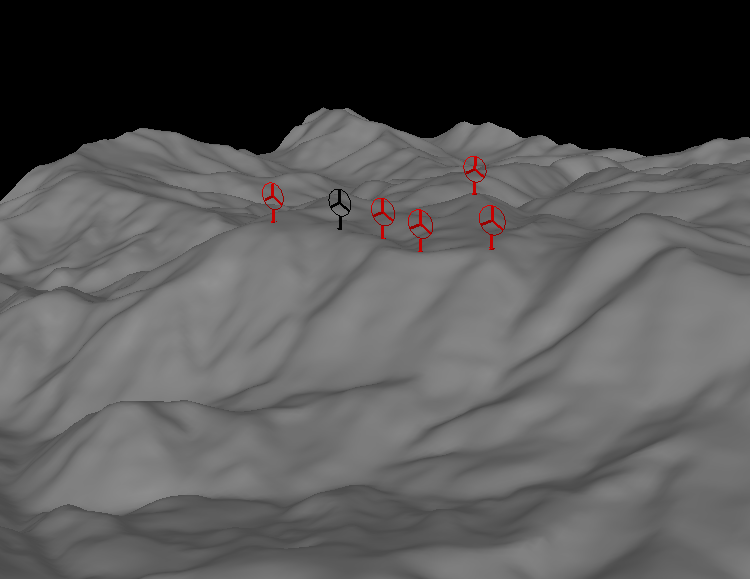
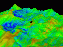
In general, wind speed increases with elevation. When wind blows up the hill, because of the speed-up effect, wind speed rises and peak at the hilltop. However, for complex terrain, this is not always the case. The mast coloured in black is 100m higher than the mast coloured in red. One would expect a higher average wind speed to be recorded at the black mast but it turns out the wind speed is almost 1m/s lower. This is caused by the presence of the obstacle-like topography located in the upstream of the black mast. As shown in the LES CFD animation result, the topography creates turbulence which travels through the mast. As a result, not only the average wind speed is lowered, the turbulence also brings a higher wind speed fluctuation and a higher frequency of gust occurrence. Gusty and turbulent locations should be avoided when choosing a wind turbine location. Therefore, it is advisable to place wind turbine (and also the mast) near where the red mast is located. Flow pattern can vary greatly over complex terrain sites. Accurate LES CFD flow simulation is essential to determine an appropriate location for your mast.
02
Evaluate Turbine Positions by LES CFD
Know the turbulence risks beforehand
Case1
Project: Taikoyama
Location: Ine, Kyoto
Country: Japan
Turbine: Lagerwey KW750-52
Installed: 2001/11
Vector
 zoom
zoomVector
 zoom
zoomTopography
 zoom
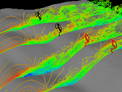
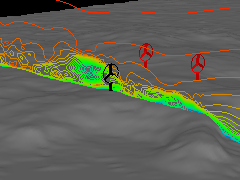
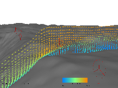
zoomAt and near the black wind turbine, LES CFD results indicate both the wind direction and wind speed are changing very rapidly. This is caused by the upstream terrain. In particular, the extremely steep and sunken V-shaped slope right next to the turbine could well be a major factor. This highly localised turbulent wind condition is causing rapid wear and frequent breakage of the yaw motor and yaw ring. Considering the excessive repair cost and the old turbine age, it has been decided to dismantle this particular turbine in the near future.
Case2
Project: Aso Kurumagaeri
Location: Aso, Kumamoto
Country: Japan
Turbine: MHI MWT-600
Installed: 2005/10
Shading
 zoom
zoomTopography
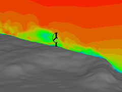
This wind turbine is located away from the ridge top. Flow separation occurred at the ridge and the generated periodic vortex is flowing through the rotor plane, which is completely engulfed in the zone of turbulent separation bubble. The high spatial wind speed variation is causing excessive loads and vibration on the blades and on the whole structure. As a result, the wind turbine was damaged and operation was stopped for 7 months. In order to prevent further damage, the turbine is now set to shut down when wind speed goes above 8m/s, significantly affecting the project economics.
Shading
 zoom
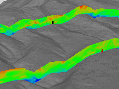
zoomSpeed Contour
 zoom
zoomTopography
 zoom
zoomThe two black wind turbines suffer from serious vibration problems when wind speed exceeds 10m/s. According to the LES CFD result, flow separation occurred at the hill located roughly 400m west of the affected turbines. Extremely high wind shear at both vertical and horizontal planes can be observed at the two turbines. This high wind shear is the cause of the vibration. To prevent excessive vibration, the two wind turbines are shut down when wind speed goes above 10m/s. Production and availability are largely decreased as a result.
Case4
Location: Australia
Turbine: Vestas V66
Installed: 2004
Speed Contour
 zoom
zoomShading
 zoom
zoomTopography
Very strong wind flowing over a coastal cliff escarpment, in which LES CFD result indicate the flow is detached at the cliff top, with recirculating vortices observed. The very severe turbulence results translates into highly fluctuating loads far exceeding the design specifications. The result is that this wind turbine suffered extensive damages including yaw gear and yaw ring breakage, gearbox failure, and large cracks in blades and nacelle frame. Wind sector management was introduced at the prevailing wind direction for the whole wind speed range in order to protect the wind turbine.
Case5
Project: Kihoku
Location: Kanoya, Kagoshima
Country: Japan
Turbine: Siemens (Bonus) 1.3MW
Installed: 2004/2
Speed Contour & Vector
 zoom
zoomTopography
 zoom
zoomFrom a total of seven years of operation data, the wind turbine on the right shows a particularly high frequency of yaw related damage when compared with the other turbines in the same windfarm. The reason for that is the turbulence caused by the undulating terrain and ridges which dominate the upstream topography. The LES CFD simulation result shows air flow is separated from the ridges and turbulence is created. Large wind speed difference is observed across the rotor plane which contributes to the yaw damage.
Case6
Project: Shinizumo
Location: Shinizumo, Shimane
Country: Japan
Turbine: Vestas V90
Installed: 2009/4
Shading
 zoom
zoomShading & Vector
 zoom
zoomTopography
 zoom
zoomOne of the blades of this wind turbine was damaged due to a tower strike incident. The terrain in the vicinity of the turbine can be described as ultra-complex, and as a result the wind flow is also ultra-complex. The extremely turbulent flow causes negative wind shear (wind speed at the bottom of the rotor is higher than at the top), as can be clearly observed from the LES CFD results. Negative wind shear led to a large blade deflection in which the blade hit the tower.
Case7
Project: Dougu
Location: Mengzi, Yunnan
Country: China
Turbine: Mingyang MY 1.5
Installed: 2012
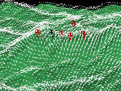
Vector
 zoom
zoomTurbine at the top of the cliff has suffered from severe vibration and analysis of turbine operation data revealed that the vibration occurred when strong wind blows from the south-west direction. LES CFD was carried to simulate the wind flow and similation predicts a flow separation at a hill upstream not far from the turbine. As a result the lower part of the turbine rotor is in a reverse flow region with highly fluctuating wind speed which contributes to the cause of the vibration. For more details, click here for technical paper.
03
Select Turbine according to Wind Conditions
Essential for stable operation and production
Choosing the right turbine for your site is like choosing the right pair of hiking shoes. Not only does it needs a good fit of your feet, but also it is vitally important to select the right type. For a short trip, trekking shoes with soft soles may be a good choice. But if you are carrying a heavy rucksack and walking for long hours, heavyweight hiking boots with stiff and durable soles are more appropriate. If you plan for river hiking, there are specialised non-slip shoes available. For cold weather hiking during winter, footwear with high ability to retain warmth is a must. To sum up, it is important to choose your footwear according to the usage and type of terrain. Similarly, when selecting a suitable wind turbine for a complex terrain site, a good understanding of the turbulence condition (usage and type of terrain) and the structural design characteristics (features of shoes) of the wind turbine is essential. Turbine design and structure can vary greatly even within the same turbulence class. A turbine which cannot withstand the site turbulence condition can break down frequently resulting in high repair costs and low availability. Conversely, using a tougher turbine that can withstand the turbulence condition can potentially avoid all these troubles and achieve stable operation. Also, when structurally weak areas come under turbulence-related shock loads, components can fail and break frequently. Based on our experience and knowledge we will have a detailed and thorough discussion with turbine manufacturers for reducing and quantifying such risk. Project life of 20 years is a long period: be cautious when it comes to selecting the right turbine for your site.
04
Carry out Suitable Inspection and Maintenance
Keep the turbines in top condition
Wind turbines are complicated machines operating in complex and often tough environments. When compared with other industrial machines, they are certainly not easy to operate and maintain; in some cases it can be an extremely difficult task. Regular inspection and careful maintenance must be carried out in order to prevent the any abnormal conditions from worsening to such an extent that prolonged breakdown becomes inevitable. Depending on the damaged section, a long wait for the arrival of replacement parts is also quite possible, translating into considerable loss of production and availability. For complex terrain sites, this is particularly an issue. This is because turbulence-induced loads and their fluctuation can far exceed the design specifications, resulting in damage of parts not normally damaged. Therefore, it is important to incorporate the effects of the turbulence and the characteristics of the machines into your inspection and maintenance services. What would you need to execute these services efficiently? A basic knowledge of the working of wind turbines is a prerequisite; but most importantly, solid experience on the operation, maintenance, repair and reform on the various specific wind turbine models.